 K0SWE Blog
PCB Project: CAT+Audio interface
I’ve taken a short break from responsible ham radio activities (like continuing on Forester) to pursue another hardware project.
My motivation is that I have been loving to use my Lab599 Discovery TX-500, but I’m getting slightly annoyed about having to remake my CAT control and audio interface “Rube Goldberg machine” every time I operate digital modes. I have a USB hub, a USB sound card, an audio Y-splitter for headset TRRS to TRS-TRS, a USB CAT cable and an audio to REM/DATA cable. It’s not that much, but it’s tedious when I have precious time in the field.
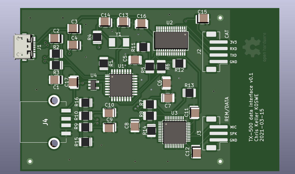
What I would like to do instead is to have a single interface box that incorporates CAT control and an internal sound card interface. This has been done by other manufacturers: the Elecraft KIO3B, Yaesu SCU-17 and the Icom 7300’s USB interface all take the approach of using a USB hub controller along with USB UART and USB sound card chip all hard-wired together on a printed circuit board (PCB) . I could probably use the Yaesu SCU-17 nearly out of the box with the TX-500 with just a custom cable, but I would like to get something smaller. Therefore, I’m taking the opportunity to “level up” my electronics and PCB design skills.
I’ve only done one custom PCB before, a K3NG CW keyer. That project
was an Arduino shield and was built with all through-hole parts. This time I want to try using an
extruded aluminum enclosure and surface mount (SMT) parts. I’m aiming to fit the entire interface
into about the size of a deck of cards, which so far seems very doable. Working with single-purpose
integrated circuits (ICs) is a new one for me, but luckily I’ve had lots of great advice, and have
found that most ICs come with application notes showing a schematic of the sorts of support parts
they expect.
I have a good start so far, but would like to breadboard this before I order boards. If you’d care to check it out, it’s open-sourced on GitHub.